Femtosecond pulse measurement instruments:
Femtosecond Autocorrelators Reef-RT
(scanning)
and Reef-SS (single-shot) -
Reef-RT -
buy online - specs
Autocorrelation technique -
Reef-RT AA-10D manual
Avoca SPIDER Spectral Phase Measurement
System - manual
Rincon Cross-Correlator Pulse Profiling
Systems - TOCC
Rincon SS Single shot third-order
cross-correlator
Optimization of Rincon TOAC for customer
laser system
IEEE JOURNAL OF QUANTUM ELECTRONICS, VOL. 35, NO. 4, APRIL 1999 501
Self-Referencing Spectral Interferometry for Measuring Ultrashort Optical Pulses
Chris Iaconis and Ian A. Walmsley
Abstract—This paper describes a novel self-referencing interferometric method
for measuring the time-dependent intensity
and phase of ultrashort optical pulses. The technique, spectral phase interferometry for direct electric-field reconstruction (SPIDER),
measures the interference between a pair of spectrally sheared replicas of the
input pulse. Direct (noniterative) inversion
of the interferogram yields the electric field of the input pulse without
ambiguity. The interferogram, which is solely a function
of frequency, is resolved with a spectrometer and recorded with a slow detector.
Moreover, the geometry is entirely collinear and
requires no moving components. This paper describes in detail the principle of
operation, apparatus, and calibration of SPIDER
and gives experimental examples of reconstructed pulses.
Index
Terms— Pulse characterization, pulse measurements, pulse reconstruction,
ultrafast optics.
I. INTRODUCTION
THERE ARE three known strategies for measuring the electric field of optical
pulses; spectrography, tomography,
and interferometry [1], [2]. The most common of these,
spectrographic techniques, such as frequency-resolved optical
gating (FROG) [3], temporal analysis of spectral components
(TASC) [4], frequency-domain phase measurements (FDPM)
[5], and spectrally and temporally resolved upconversion technique
(STRUT) [6], measure a two-dimensional (2-D) representation
of the one-dimensional (1-D) field and consequently
require the collection of a relatively large amount of data.
Moreover, unless the pulse has a simple structure, spectrography
requires sophisticated iterative data inversion algorithms
to reconstruct the field. Tomography also requires a large 2-D
data set, but data inversion is direct (noniterative). In practice,
however, it is difficult to fabricate a tomographic apparatus
with a bandwidth of several terahertz and, consequently,
tomography has not been applied to ultrafast pulses, although
tomographic-like methods that require iterative inversion have
been demonstrated [7]. Interferometry, in contrast, requires
only a 1-D data set to reconstruct a 1-D field and uses
direct data inversion to do so. Diels has demonstrated an
interferometric method that uses an ultrafast photodiode and
Schottky diode nonlinear mixer to record the beat notes
more
Femtosecond Autocorrelators Reef-RT
(scanning)
and Reef-SS (single-shot) -
Reef-RT -
buy online - specs
Autocorrelation technique -
Reef-RT AA-10D manual
Avoca SPIDER Spectral Phase Measurement
System - manual
Rincon Cross-Correlator Pulse Profiling
Systems - TOCC
Rincon SS Single shot third-order
cross-correlator
Optimization of Rincon TOAC for customer
laser system
NEW
Avoca 7 SPIDER
Specifications
Wavelength range 600 ÷ 1060 nm
Pulse duration 6 ÷ 25 fs
Minimum required input power 300 mW average for 100 MHz repetition rate;
5 mW for 1kHz repetition rate.
Input polarization horizontal
Input beam diameter 2 ÷ 4 mm
Input beam height 110 ÷ 140 mm
I. The principle of operation of AVOCA SPIDER 7 . The principle of operation of AVOCA SPIDER 7 is a version of spectral shearing interferometry1,2 (SSI). This version is known as SPIDER – Spectral Phase Interferometry for Direct Electric field Reconstruction 3, 4. In SSI the pair of replicas of the tested ultrashort light pulse
are shifted in frequency with respect to each other and then are interfered in spectrometer.
A very simple noniterative algorithm of recorded spectral interferogram gives the spectral
phase of ultrashort light pulse to be characterized . In addition with independently measured pulse spectrum after Fourier transform the time-dependent phase and intensity is obtained .
The scheme of SPIDER apparatus is shown in Fig.1. Two identical pulse copies are delayed with respect to one another by time t and frequency mixed with a stretched pulse in
a nonlinear crystal. Each pulse replica is upconverted with a different frequency slice, and consequently, the upconverted pulses have a spectral shift. Note, that the central frequency of the upconverted pulses is near 2 wo (wo is the central frequency of measured pulse).
The output signal S (wc) of spectrometer is related to the input pulse spectrum by
S(wc)=|Ẽ (wc)|² + |Ẽ (wc +Ω)|² + 2| Ẽ(wc)||Ẽ(wc +Ω)|
õ cos [Φω(ωc + Ω) - Φω(ωc) + wcτ] (1)
Where Ẽ (w) is the complex representation of the input pulse electric field, Ω – is the frequency shift, τ is the time delay between the two replicas, and wc is the variable center
passband frequency of the spectrometer. The first two terms on the right side of (1) are the
individual spectra of the test pulse and its frequency shifted replica, respectively. The third term provides the spectral phase in the form of the phase difference between spectral components separated by the shear Ω. One obtains the spectral phase for a set of discrete frequencies separated by Ω from the spectral phase difference by simply adding up the
appropriate phase differences. The spectral amplitude at these frequencies is obtained from
the square root of an independently recorded pulse spectrum.
An example of the experimental spectral interferogram of a pair spectrally shifted pulses is shown on Fig.2. The nominal fringe spacing is 1/τ (in linear frequency units). Spectral phase of the tested pulse manifests itself as deviations from the nominal fringe spacing.
To extract the spectral phase from the experimental interferogram the robust direct (noniterative) inversion procedure is used. This procedure is diagrammed schematically in Fig.3. The Fourier Transform of the experimental interferogram from Fig.2 is shown in Fig.4.
The component centered near t = + τ is filtered and inverse transformed back into frequency
domain.
The next step of the phase reconstruction procedure is to remove the linear phase term
τwc from (1). The most reliable method to do it is a direct measurement of τwc. The interferometer is calibrated by recording a spectral interferogram for the pair pulses without
imparting the spectral shear. In this case, the interfered pulses are identical and therefore the only phase contribution is τwc. The linear phase obtained from calibration is simply subtracted from Φω (ωc) - Φω(ωc - Ω) + τwc.
On subtracting the term proportional to τ from the resulting phase distribution we are left with the relative phase, Φω(ωc + Ω) - Φω(ωc), between successive pairs of frequency components separated by Ω. The spectral phase for a discrete set of frequencies separated by
Ω is constructed by concatenation. This inversion procedure is noniterative; the phase is directly retrieved from the data by a series of linear transformations. Thus, given appropriate data, the reconstruction error associated with the inversion routine is zero. Of course the accuracy of the reconstruction is limited by the signal-to-noise ratio of the experimental data,
as it is for all methods.
1. V. A. Zubov and T. I. Kuznetsova, Laser Phys. 2, 73 (1992).
2. V. Wong and I. A. Walmsley, Opt. Lett. 19, 287 (1994).
3. C. Iaconis and I. A. Walmsley, Opt. Lett. 23, 792 (1998).
4. C. Iaconis and I. A. Walmsley, IEEE J. Quantum Electron. 35, 501 (1999).
II. The description of AVOCA SPIDER 7 apparatus
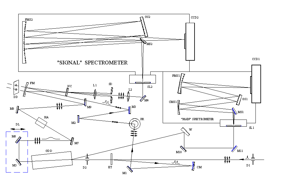
The optical scheme of AVOCA SPIDER 7 device is shown in Fig.5. The direction of the input
horizontally polarized beam is fixed by the diaphragms D1 and D2. The reflections from
the front and back sides of an uncoated fused silica ethalon ET are used as the two time delayed replicas of the input pulse . Thickness of ethalon is equal 38 microns, and time
delay τ between these two reflections is approximately 375 fs. After the reflection by mirrors CM, M1 and two-mirror Polarization Rotator PR the polarization of the replicas is changed from horizontal to vertical. Then with the help of the flat mirrors M2,M3 and the spherical (radius of curvature 200mm) Focusing Mirror FM the test pair of replicas is focused into Nonlinear Crystal NC. The most part of the input pulse passed through the ethalon and diaphragm D2 then stretched in the glass stretcher consisted of high dispersive TF5 glass slab 75mm in length.
The stretched pulse after leaving the stretcher passes the delay line DL and reflected by flat mirrors M7, HA (Height Adapter), M8, M9 and focusing mirror FM is focused on Nonlinear Crystal NC.
The parallelness of the stretched beam and the test pair beam falling on FM is providing
by appropriate adjustment of the M2 and M3 mirrors. These two beams should be parallel and lay in vertical plane with the most possible accuracy . The optical passes of the stretched pulse and a pair of test pulses from the ethalon to the focus of FM where NC is placed
is equalized by Delay Line DL in the stretcher. Note that the stretcher beam and the test pair beam are polarized in the perpendicular directions. So to upconvert the test pair with the stretched pulse Type II 40μ BBO crystal in non-collinear geometry is used. The NC is cut for phase matching at λo =800nm and λe =800nm ( φ=0o, θ=43º) and oriented so, that the test pair of pulses polarized along the ordinary axis. For this orientation of NC its bandwidth is considerably broader then when rotated through 90º. The Type I (φ=90o, θ=32º) 10μ BBO crystal is used to record the Reference spectrum.
The upconverted beam passes through Lens L1, Slit Diaphragm SD and focused by Lens L2 ( both lenses with focal length 60mm) at the entrance slit- SL2 of “SIGNAL” SPECTROMETER. The input pulse spectrum is recorded by the “MAIN” SPECTROMETER . For this purpose the reflection of the input pulse from TF5 glass slab GDD is used. This reflection with the help of the wedge W and two flat mirrors M10 and M11 comes to the entrance slit SL1.
These two diffraction grating spectrometers allow the simultaneous recording of the input pulse spectrum in the range 600÷1060nm and the upconverted spectral interferograms in the range 345÷455nm. The recording of the spectra is carried out by two one- dimensional CCD arrays CCD1 and CCD2. Every CCD array has 1024 pixel with pixel size 25μ (W)x 500μ(H).
III. Software Installation
Efrat Software Installation and Configuration Notes
-----------------------------------------------------------------------------
I. REQUIREMENTS
o IBM PC compatible computer
o Processor > 600 MHz
o RAM > 128 MB
o HDD space for installation 10 MB
o Video 1024x768 HighColor or better
o USB port
o Microsoft Windows 98SE/ME/2000/XP
II. SOFTWARE INSTALLATION
The software distribution consists of EfratSetup-3.2.1.0-Ormins-Ormins_1.exe
executable file and a set of files in Presets folder. These files contains the
information on spectral calibrations and sensitivity for spectra registration
system recorded during device fabrication. The folder Presets must be
located in the same folder as setup executable.
To install software:
o Run EfratSetup-3.2.1.0-Ormins-Ormins_1.exe by double-clicking it
in Windows Explorer. (If you have CD distribution and autoplay
for CD-ROM enabled then setup will start automatically after CD
insertion). On Windows 2000/XP you must have administrator privileges
to install software. The Setup Wizard will guide you for the software
installation process.
o Select 'OrminsCCD USB (SINGLE Head) DAQ Driver' item in the Components
page of a Setup Wizard to install spectra registration CCD driver on
your system.
o The driver requires vendor supplied operating system device driver
to access data acquisition hardware through the USB interface. You
select 'Install OS driver' in the Additional Tasks page of a Setup
Wizard to install vendor supplied device driver. This will launch
vendor supplied Setup Wizard. You use default settings proposed by
this wizard and wait until it finished its tasks. Then you select
'I want to restart my computer now' option from Setup Finished
page of a main Setup Wizard to complete software installation.
III. HARDWARE INSTALLATION
o Connect devices units to the computer using supplied USB cables.
o Check that device OrmisCCD appeared in the Device Manager under
USB Controllers branch. (In some cases Windows may try to
reinstall OS driver and launch 'New hardware found' wizard.
Follow the wizard and select the device driver found on the system).
IV. DRIVER CONFIGURATION
o Launch Efrat using Windows Start menu or desktop shortcut. The main
window of the application will be opened.
o Under 'Acquisition' menu choose 'Configure drivers...' item. The
Drivers List dialog box will be opened.
o In Drivers List dialog box click the 'Add...' button. With the
Open dialog box navigate to the folder where you've installed
Efrat, and then to subfolder DRV\OrminsCCD. Select file named
OrminsCCD1.dll and click the 'Open' button. The OrminsCCD Configuration
dialog box will be opened (the device must be connected to computer
at that time).
o In the OrminsCCD Configuration dialog box you'll see device
serial number and selected check box to the left of it. Just
click 'OK' button in this dialog box. Two spectra acquisition
window will be opened.
o Now you click 'Close' button in the Drivers List dialog box (or you
will be unable to access the application main window).
V. LOADING SPECTRAL CALIBRATION
o In spectra acquisition window named by default 'Device:OrminsCCD<0>'
click on the down arrow to the right of the 'Calibration...' button.
Choose 'Load...' item in the popup menu.
o Navigate the folder where you've installed Efrat and select the file
named 'mainsp_7.SCL'. Click the 'Open' button. Now you have spectral
calibration loaded to that spectrum channel.
o Repeat two previous steps with spectra acquisition window named
'Device:OrminsCCD<1>' but open the file named 'signalsp_7.SCL'.
VI. LOADING SPECTRAL SENSITIVITY DATABASE
o In main window choose 'Sensitivity database...' under "Acquisition'
menu.
o Click the 'File' button and choose 'Merge...' item in the popup menu.
o Navigate the folder where you've installed Efrat and select the file
named 'spsensmainsp7.SDB'. Click the 'Open' button. Now you have spectral
sensitivity data loaded to the program.
o In spectra acquisition window named 'Device:OrminsCCD<0>' click on
the down arrow to the right of the 'Equalization...' button. Choose
'Setup...' item in the popup menu.
o In 'Availabe Sensitivity Curves' list select ''spsensmainsp7.SDB'' item and
press '>' button move it to 'Selected Sensitivity Curves' list. Click
'OK' button to finish this setting.
VII. END NOTE
All settings you've made will be recorded in the program configuration file
and will be restored when you launch Efrat again. For more information on
the software operation see online help (available under 'Help' menu in
the main window of Efrat) and other supplied documentation.
IV. Unpacking of AVOCA SPIDER 7 device.
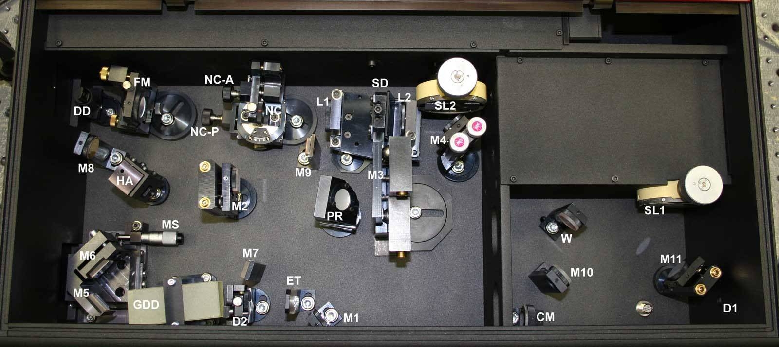
Carefully extract the device from the transportation box and very carefully mount it on your optical table. Use the height adjusting legs to mount the device horizontally and to choose the beam height you need. Reliably fix the legs to optical table by applied cramps. Lift the cover and accurately remove the transportation protector from MS (See Fig.6).
V. Measuring Procedure
Before you start Measuring Procedure, please look through Efrat-software Help.
Also you should check the input pulse power. For the first time it should be: 300-500mW average for 100MHz repetition rate and 5-10mW for 1 kHz repetition rate. The beam diameter shouldn’t exceed 4mm (at 1/e2 intensity level) . The better value 2-3mm. AVOCA SPIDER 7 also expects a collimated beam without spatial chirp.
1. Using the outer fold mirrors let the input beam pass through the installed flip diaphragms D1 and D2 with the most accuracy.
2. Flip down the diaphragms D1 and D2.
Attention! Be careful when flip down D2 – don't touch the ethalon ET!
3. Check the parallelness of the stretched and the test pair beams. For this purpose carefully flip down the focusing mirror FM in horizontal position and let these two beams pass through the double diaphragm DD (See Fig.5 and Fig.6 ). Remove the side cover just behind DD and check the beam spot separation at the distance 3÷4 meters far from DD. The beams should lay in vertical plane and beam separation at mentioned above distance should be the same as at DD – approximately 8 mm.
Warning! The stretcher beam direction is factory maintained and need not for correction. Use only the alignment with the help of M2, M3 mirror.
4. Slowly return the focusing mirror FM in vertical position.
5. Set up the width of SL1 of “Main” Spectrometer in the range 30 ÷50 μm . Turn on the “Autorun” mode on CCD<0> window of Efrat – software. Set up the exposition time of CCD 10÷20ms and switch off the “Equalization” button. Changing the SL1 width and exposition time set up the maximum value of the input pulse spectrum signal in the range 3000÷12000 a.u. Shut the input beam and correct the zero-line by “Baseline” button. This correction should be carried out every time you run Efrat and after every exposition time changing.
6. Unfix the adapter with Nonlinear Crystal NC (10μ Type I BBO for pulses 6- 12fs duration or 40μ Type II BBO for 12-25fs duration )and rotate it in the position for recording the Reference spectrum. In this position Red mark on NC-adapter should be matched with White mark on NC mount. Fix the adapter again.
7. Set up the width of SL2 in the middle position ~200μm.
8. Translate the Slit Diaphragm SD in the position allowing to pass the test pair beam only – the lower beam spot after NC.
9. Check the maximum value of the CCD<1> signal ( Reference spectrum). This signal shouldn’t be saturated. The saturation level is ~ 16000am. If the signal is saturated, then slowly close the SL2 width. Using M4 mirror adjustments try to get the maximal signal for the minimal SL2 width. This maximal signal value shouldn't exceed 13500-14500 a.u.
Note, that the signal level also depend on the central wavelength of the input pulse spectrum because NC is factory phase matched for the central wavelength λc =800nm. If the central wavelength of the input pulse spectrum differs of 800 nm , then you need to adjust NC for this wavelength . For this purpose use Nonlinear Crystal Adjustment Screw NC – A . After optimizing the Reference signal level record it to your Efrat reconstruction project.
10. To record the Signal spectrum only Type II 40μ NC is used . So if you recorded the Reference spectrum with the help of Type I 10μ NC you should replace it by Type II 40μ NC and match White marks on NC adapter and NC mount. If you used Type II 40μ NC for recording the Reference spectrum then you simply unfix the adapter NC and rotate it by 45˚ to the position for recording the Signal interferogram or simply Signal as it named in Efrat – software. In this position the White mark on NC adapter should match with the White mark on NC mount . Fix NC adapter again.
11. Slowly rotating Delay Line microscrew MS (See Fig.6) set its position around 4.30mm. This position corresponds the upconversion with wavelength near 800nm of the stretched beam.
12. Translate the SD in the position allowing to pass only noncollinear upconverted beam and simultaneously blocking the stretched and test pair beams.
13. Optimize the Signal value slightly adjusting M4 mirror and the SL2 width as it described in the Subsection 9 of Measuring Procedure. Check the parallelness of the stretched and the test pair beams slightly adjusting only M3 mirror and trying to maximize the Signal value. Then try to maximize the Signal by NC adjustment as it described in the subsection 9. If the adjustments of M3 or NC is changed to compare with the recording Reference Signal it is necessary to record the new Reference signal with these new adjustments of the M3 and NC and then continue the Signal acquisition .
14. To reconstruct the input pulse you should introduce the Stretcher parameters. These are: Slab material – TF5 Glass; Slab length – 75mm.
15. If the repetition rate of the tested laser pulses is 10Hz or less you should use the outer synchronization of CCD. For this purpose connect the both CCD synchronization ports and
the synchronization pulse source by means of supplied cables marked by the arrows directed from the synchronization source toward the CCD camera. The synchronization pulse should be positive, 5-20V in amplitude (the input impedance of the synchronization port is 11 kOhm) and precede the laser pulse 1.5ms or more at the level 1-1.5V. Another synchronization cable (marked by arrows directed from the CCD camera) should be used if for some purpose you need in CCD camera output synchronization pulse.
Femtosecond pulse measurement instruments:
Femtosecond Autocorrelators Reef-RT
(scanning)
and Reef-SS (single-shot) -
Reef-RT -
buy online - specs
Autocorrelation technique -
Reef-RT AA-10D manual
Avoca SPIDER Spectral Phase Measurement
System - manual
Rincon Cross-Correlator Pulse Profiling
Systems - TOCC
Rincon SS Single shot third-order
cross-correlator
Optimization of Rincon TOAC for customer
laser system